
|
Commenced:
|
01/08/2007 |
|---|---|
|
Submitted:
|
15/02/2011 |
|
Last updated:
|
23/10/2015 |
|
Location:
|
PO Box 14, Karat Konso, SNNPRS, ET |
|
Phone:
|
+251 912 21 46 87 |
|
Website:
|
www.permalodge.org |
|
Climate zone:
|
Dry Tropical |
(projects i'm involved in)
Back to Strawberry Fields Eco Lodge
Project: Strawberry Fields Eco Lodge
Posted by Alex McCausland about 11 years ago
Water Source
Our only current water source for potable water and garden irrigation is the Konso Town municipal supply which is drawn from a bore-hole situated just across the road from our site entrance. The supply facility is a manned pumping station with an electric water pump, backed up by a diesel pump for times of power outage, which are frequent. Even this back-up pump may fail on occasion due to lack of fuel or mechanical fault. There are also times when there is a problem in the water line, meaning that the municipal water supply is far from reliable. There are occasional water supply failures of up to a weak, perhaps once a year, and more frequent shorter failures of 1 to 3 days every few months. These failures seem to be more frequent during the dry season when there is additional pressure on the system to supply greater community needs. When there is water, the supply is usually on for a couple of hours in the morning 5am – 7am and evening 4pm – 6pm.
The main supply line enters our site directly from the water pump station under the road via the storm drains situated just to the north of the old foot entrance, delivered by a ¾” poly-pipe.
Storage Capacity and Tank Distribution
Our water system currently in use has a severe lack of storage capacity. Due to the relatively very high price of water storage containers on the Ethiopian market the project has been severely budget constraints in developing adequate water storage. The total water storage capacity is currently only 4000 litres held in four 1000l plastic tanks located at 4 different points.
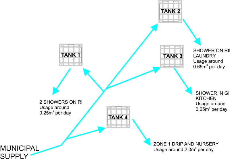
One tank (Tank 1) is situated on ridge 1 just next to T3. This serves the showers on ridge 1, between T2 and T3 and between T4 and T5. This tank is set at a vertical elevation of 2.5m above ground level on the ridge top upon a tower made using rammed earth tyres and old oil drums filled with gravel.
Map 1: The Currently Existing Water System at Strawberry Fields Eco Lodge, Konso
Main distribution line in dark blue, secondary distribution from tanks in light blue
A second tank (Tank 2) is situation at the top or RII just below the highest point on the site. It serves the shower between T6 and T7, as well as the laundry which is located behind T6. Due to its location the tank is already at a height advantage relative to the shower and laundry, so does not need a tall tower to give head-pressure. It is set on a stand made from steel pipe which is only 1m above ground level.
A third tank (Tank 3) lies on RII just to the north of T9. This serves the newer shower at the base of the ridge in GI as well as the kitchen. Again due to the location a high tower is not needed and this tank is elevated only 1m above ground level on a stand comprised of old oil drums.
The fourth tank (Tank 4) is set in the Zone 0 area, just to the east of the kitchen building. This tank serves the Zone 1 drip system and tree nursery in the adjacent Zone 1 area. It is set on a reinforced concrete stand of 1.5m vertical height.
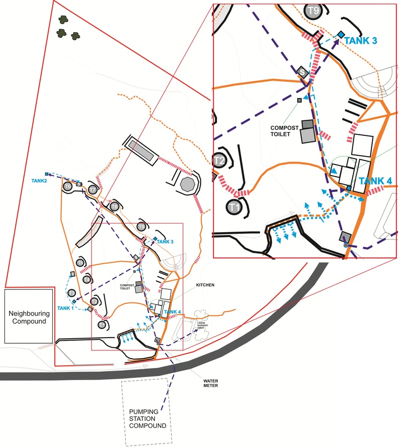
Pipes and Distribution
The water meter is located just next to the seed-bank building. From here the main line (½”) runs directly up to the tank at the top of RII. There are 4 side branches leading off the main line. One just after the meter itself which leads to the large tree nursery area in the Zone II area next to the large low pond in the main gulley. The second branch off is at the kichen leading to the tank which supplies the Zone I drip system. The third and fourth branches are at the bottom of the steps leading up the side of RII just below tukul T9. These branches lead to the tanks next to T3 (on RI) and T9 (on RII).
Water Usage
|
Use |
Average Volume m3/day |
Current Tanks Serving Use |
|
Showers |
0.5 |
1, 2, 3 |
|
Laundry |
0.5 |
2 |
|
Kitchen |
0.5 |
3 |
|
Garden |
2 |
4 |
|
Total |
3.5 |
|
Capacity
As can be seen from the table the project water usage at busy times (when there are a lot of guests in the lodge and eating in the restaurant) roughly averages 3 – 4m3 per day. This means the total water storage capacity of the project is only a single day’s usage.
Management
Due to the distribution of the current tanks as well as their small capacity there are also problems with the management of the water even when availability is not an issue. Available pipe fixtures and fittings are of very poor quality in Ethiopia as are the technical skills for installation and maintenance. Meanwhile the pumping station which is just across the road from us pumps water several kilometres up-hill to the town. As a result the water reaching us from just across the road is at extremely high pressure which the fittings, especially valves, struggle to deal with. Consequently the available float-valves we have installed here have failed time and again, meaning that management of the water tanks has to be conducted manually on a daily basis.
One worker is assigned to do this. However since the water is only on for a limited period each day, that worker may miss the opportunity to fill the tanks if he gets distracted by some other occurrence or task. On the other hand water spillages may occur when the tap is left open if the worker forgets to close it in time. This problem has been a regular occurrence.
Improving the System
In re-designing the current a new system we have the following aims:
1) Making it easier to manage IE giving a larger margin for error if someone forgets to switch a tap on or off!
2) Having a degree of de-centralisation so that reserves are split between uses but without complicating the management. Partitioning reserves also protects against total loss in the case of a disaster.
3) Allowing it to catch and store rainwater as well as bore water from the municipal system, but having a system to clean detritus out of the rainwater so it does not block up the irrigation system.
4) Feeding through to water treatment and re-use systems through a cascade in vertical space with declining use-value
A better water system will be both easier to manage and have a larger reserve capacity. The key to this is larger tanks, if capital can be acquired for this purpose. Implementing this design up-date for the water system will require an investment of around $3000 which is sufficient to purchase 200m of ¾” poly-pipe and 2 x 10,000l tanks. All of the currently existing pipes, tanks and fittings will be re-integrated back into the system with minimum changes – following the principal of “least change for maximum effect”.
New System Design and Features
1) Larger tank capacity – The current 1000L tanks need to be filled almost daily and each take around 20 – 30 minutes to fill. This is long enough that standing there waiting becomes very tedious but not long enough that you could forget for a couple of hours and it wouldn’t matter. It would be much more effective if we could develop a larger capacity system with so that it would only need to be filled up every 3 – 5 days. This suggests a capacity of around 20,000L – 5 times the current capacity. A 10,000L tank would take about 2 – 3 hours to fill. This is actually longer than the water is usually on for, so the tap could just be opened and the tank checked again at hourly intervals, and switched off if required.
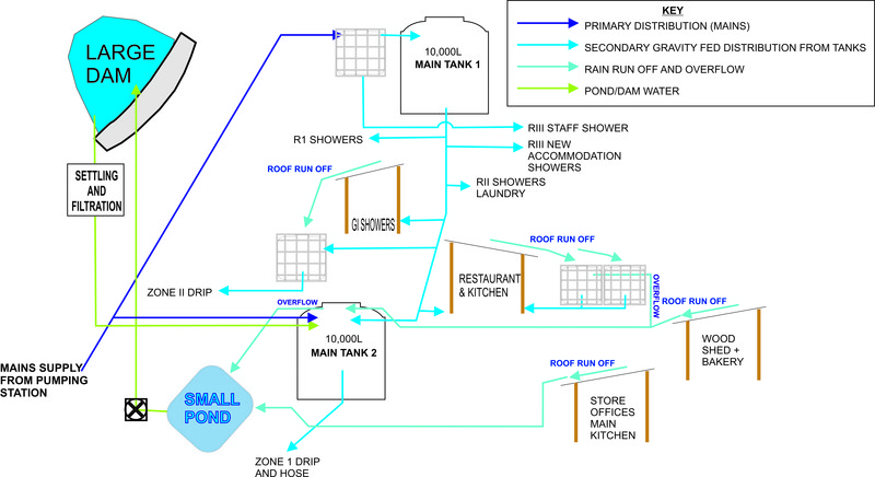
2) Fewer main storage reservoirs – instead of having 4 reservoirs the new system design only has 2. Two main tanks instead of 4, means half the number of valves to deal with opening and closing, again making management easier. Two of these tanks will give the system a capacity of these tanks integrated into the system with the 4 current small tanks will give a total capacity of 24,000L.
3) Partitioning for specific purposes – tanks can be joined together in different ways. Joining two tanks at the bottom makes them effectively a single tank. The water level in the lowest tank determines the overall capacity of the joined tanks. Joining tanks at the top means one tank overflows into the other. The reserves remain effectively partitioned. We can use this technique to partition a reserve of water for a specific purpose. For example in the new water system design outlined here, we fill through a 1000l tank into the 10,000l Main Tank 1. This means the mains will fill the 1000L tank first and then overflow into the larger tank. This small tank feeds our staff shower, so allows us to limit the amount of water being used by the staff. Also if a tap gets left on or some other miss-hap, we’ll know about it and we also won’t loose a huge amount of water.
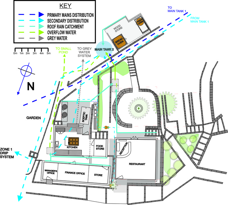
Map 2: The New System Design In-Situ on the SFEL Site Plan
4) Connections between tanks to allow partitioning and back-up if required – The vertical positioning of the reservoirs as well as their connections to each other determines how we direct the flow of water between them and the other parts of the system. Partitioning the reserves is a safety measure, however if part of the system goes dry due to unforeseen circumstances, the best design will give us the opportunity to divert water from one of the other reserves to the empty section. Hence our Main Tank 2, which supplies the garden (the element with the highest water use) can be filled not only direct from the mains but also by a connection from main tank 1, which lies up-hill.
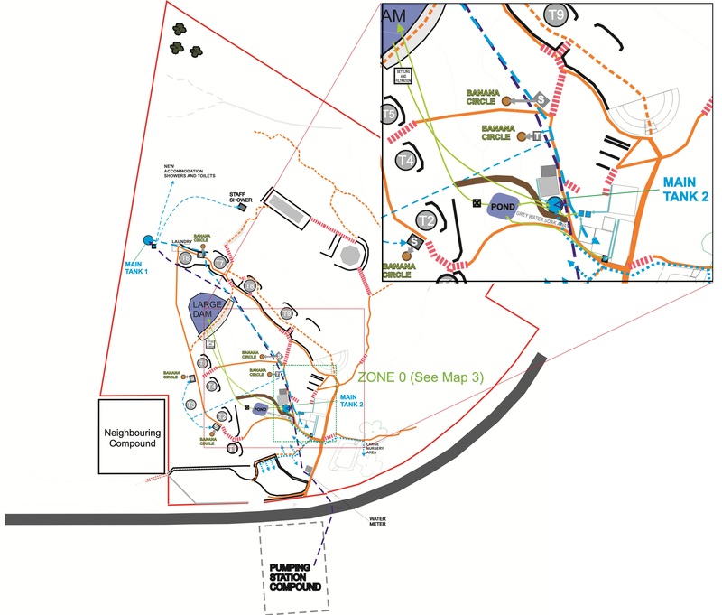
5) Integrating water inflow from roof rain water catchment, via holding tanks and detritus sieves, into the main water system. The main roof catchment surface area on the project is from the kitchen, restaurant, offices and sore (called “the Zone 0 complex” in our project design) which has a total surface area of around 123.5m2. With our annual average rainfall of 800mm we should be able to harvest about 100m3 of water off this roofing per year. Additionally the bakery/woods shed building has a roof area of around 22.5m2 from which we should be able to harvest another 18m3. In the design we have thus placed two 1000l tanks to catch water from the restaurant (36m2) and back kitchen shelter (20m2) roofs respectively. These will have sieves to catch detritus washing off the roofs. The water in these tanks will be used directly in the plate washing area, next to which they are situated. However the overflow will spill into the large Main Tank 2. This is situated next to the bakery/wood shed. It receives water directly from the bakery roof, but also gets the overflow from the two smaller tanks, when the rain is more than the kitchen can use. Main Tank 2 itself then overflows into the small pond situated in the middle of lower Gulley I.
6) Integrating the piped water system with our bulk water harvesting and storage. The small pond itself (as we outlined in our previous article) is used as a bulk water harvester. In the design, it not only receives water from Main Tank 2 but also all the rain water harvested from the main kitchen roof (31.5m2) and the store and offices (36m2). It is also intended to develop our grey water treatment system to be able to discharge effectively treated clean water into this pond, especially during the rainy season. The idea is to pump all the water accumulating here up into a large dam which is situated in upper Gulley I. This dam has been built but needs to be dug out deeper and lined, due to the high permeability of the soil. The dam, with a potential capacity of 200m3 will also receive water from our flood water harvesting system outlined in the previous article. So we plan to fill the dam to capacity over the course of a rainy season, so that it holds enough water to supply the drip Zone 1 drip and nursery requirements for 100 days, which is the main part of the dry season. This will allow us to greatly reduce our reliance on bore water.
Map 3: Close New System Design in Zone 0 Complex Area
System Implementation
To make implementation as easy and cost effective as possible, we need to make use of the currently existing infrastructure to the maximum possible effect with the least change. The pipes used in the current system for mains distribution, shown in Map 1 (dark blue,) will be re-utilized without removing or adjusting them. They will be used in the new system for secondary distribution, shown in Map 2 (light blue), which is convenient since the existing system already runs to all the usage points. This saves us a lot of work, since the piping is already in position for that purpose, it’s just a question of changing a few connections. The new mains distribution pipe (Map 2, dark blue) needs only to be connected to the water meter and runs directly up to Main Tank 1, at the highest point, with only one side branch at Main Tank 2, which is next to the bakery/wood shed. The only real adjustments to make to the current system are in terms of re-distribution is to extend a connection from the new Main Tank 2 down to the Zone 1 drip system and on into the large tree nursery next the large low-pond in the main gulley.
The next part of the water system to consider is the grey water treatment system, which I’ll tell you about in the next report. We are planning to start implanting these systems during our 4-week practical group internship which we will be running at our site in April-May following our PDC course. If you want to learn about designing and implanting systems like these, come along and help us out.
You must be logged in to comment.


Note: The various badges displayed in people profiles are largely honesty-based self-proclamations by the individuals themselves. There are reporting functions users can use if they know of blatant misrepresentation (for both people and projects). Legitimacy, competency and reputation for all people and projects can be evidenced and/or developed through their providing regular updates on permaculture work they’re involved in, before/after photographs, etc. A spirit of objective nurturing of both people and projects through knowledge/encouragement/inspiration/resource sharing is the aim of the Worldwide Permaculture Network.
 |
MemberA member is a permaculturist who has never taken a PDC course. These cannot become PDC teachers. Members may be novice or highly experienced permaculturists or anywhere in between. Watch their updates for evaluation. |
|---|---|
  |
Permaculture MatchmakerOne of these badges will show if you select your gender and the "I'm single, looking for a permaculture partner" option in your profile. |
 |
PDCPeople who claim to have taken a Permaculture Design Certificate (PDC) course somewhere in the world. |
 |
PDC VerifiedPeople who have entered an email address for the teacher of their PDC course, and have had their PDC status verified by that teacher. Watch their updates for evaluation. |
 |
PRI PDCPeople who’ve taken a Permaculture Research Institute PDC somewhere in the world. |
 |
PDC TeacherPeople who claim to teach some version of PDC somewhere in the world. |
 |
PRI TeacherWith the exception of the ‘Member’ who has never taken a PDC, all of the above can apply to become a PRI PDC Teacher. PRI PDC Teachers are those who the PRI recognise, through a vetting board, as determined and competent to teach the full 72-hour course as developed by Permaculture founder Bill Mollison – covering all the topics of The Designers’ Manual as well as possible (i.e. not cherry picking only aspects the teacher feels most interested or competent in). Such teachers also commit to focussing on the design science, and not including subjective spiritual/metaphysical elements. The reason these items are not included in the PDC curriculum is because they are “belief” based. Permaculture Design education concerns itself with teaching good design based on strategies and techniques which are scientifically provable. PRI PDC Teachers may be given teaching and/or consultancy offerings as they become available as the network grows. |
 |
Aid WorkerThe individual with this badge is indicating they are, have, or would like to be involved in permaculture aid work. As such, the individual may or may not have permaculture aid worker experience. Watch their updates for evaluation. |
 |
ConsultantThe individual with this badge is indicating they are, have, or would like to do paid permaculture design consultancy work. As such, the individual may or may not have permaculture consultancy experience. Watch their updates for evaluation. |
 |
Community ProjectCommunity projects are projects that help develop sustainable community interaction and increase localised resiliency. |

